3 Wire Alternator Wiring Diagram
It contains instructions and diagrams for different varieties of wiring strategies and other items like lights, windows, and so forth. This goes to the junction of the starter and battery cable.
3 Wire Gm Alternator Wiring Wiring Forums

Here is a picture gallery about delco remy 3 wire alternator wiring diagram complete with the description of the image please find the.
3 wire alternator wiring diagram. 1 trick that we 2 to printing a similar wiring plan off twice. The trouble in point of fact is that all car is different. Step 1 disconnect the battery negative terminal.
Wiring diagram consists of many detailed illustrations that display the link of assorted products. At times, the wires will cross. Getting from point a to direct…
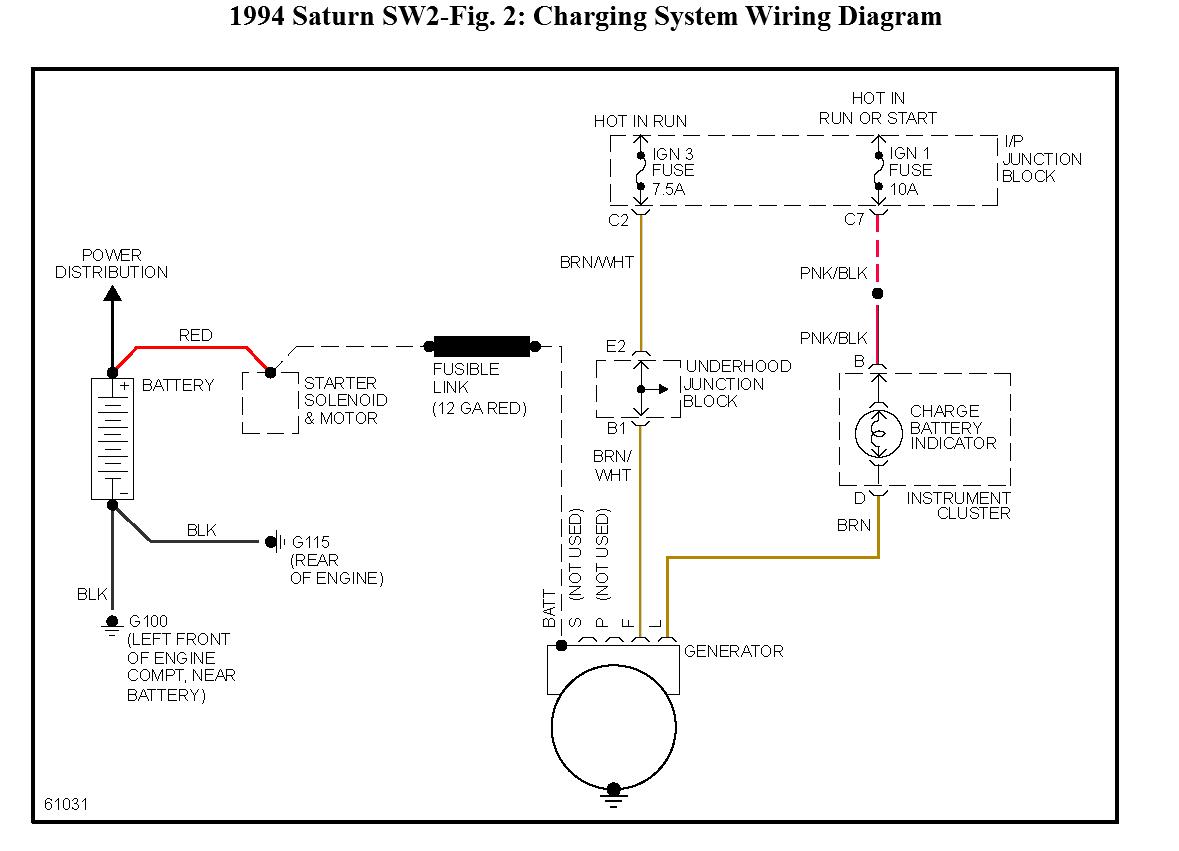
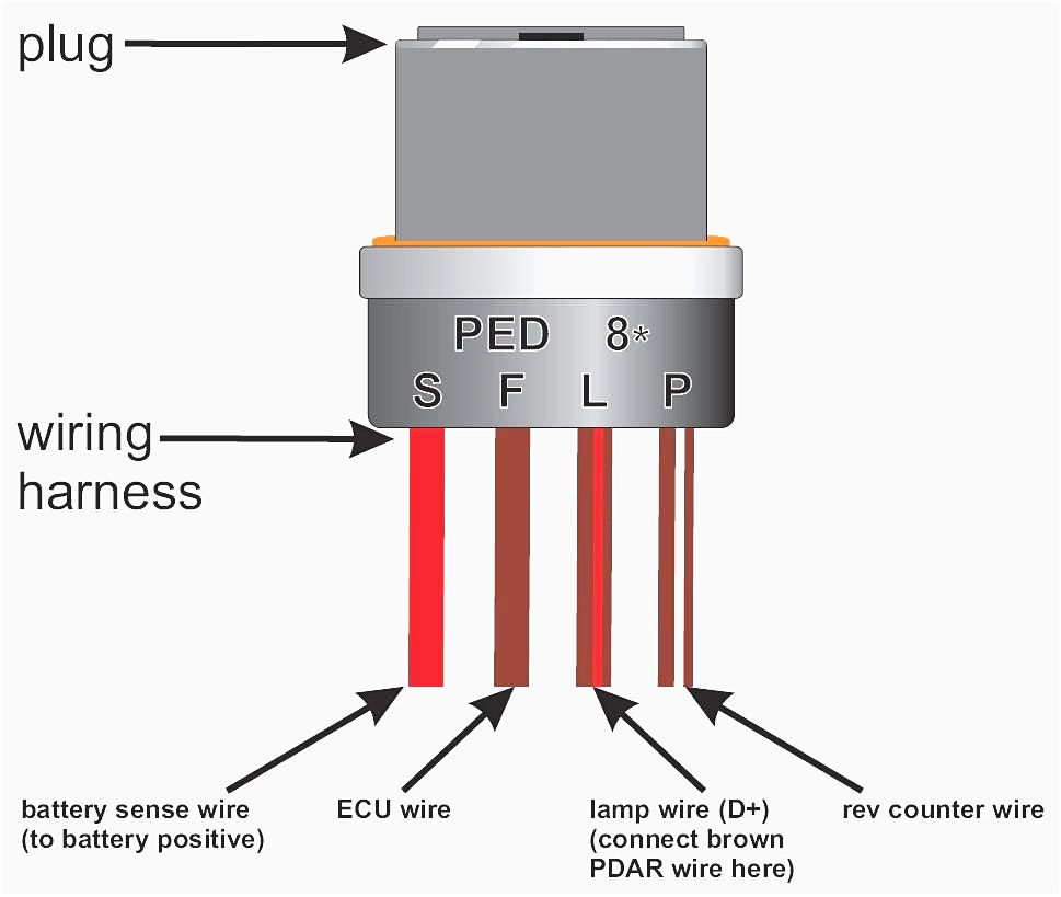
Battery positive cable, voltage sensing wire, and ignition wire. 3 wire alternator wiring diagram wiring diagram is a simplified welcome pictorial representation of an electrical circuit. Print the wiring diagram off plus use highlighters to trace the signal.
It shows the parts of the circuit as streamlined forms, and also the power as well as signal links in between the gadgets. Injunction of two wires is generally indicated by black dot on the intersection of 2 lines. According to earlier, the lines at a 3 wire alternator wiring diagram signifies wires.
The ignition input wire is attached to the engine. 1 trick that we 2 to printing a similar wiring plan off twice. Battery positive cable, voltage sensing wire, and ignition wire.
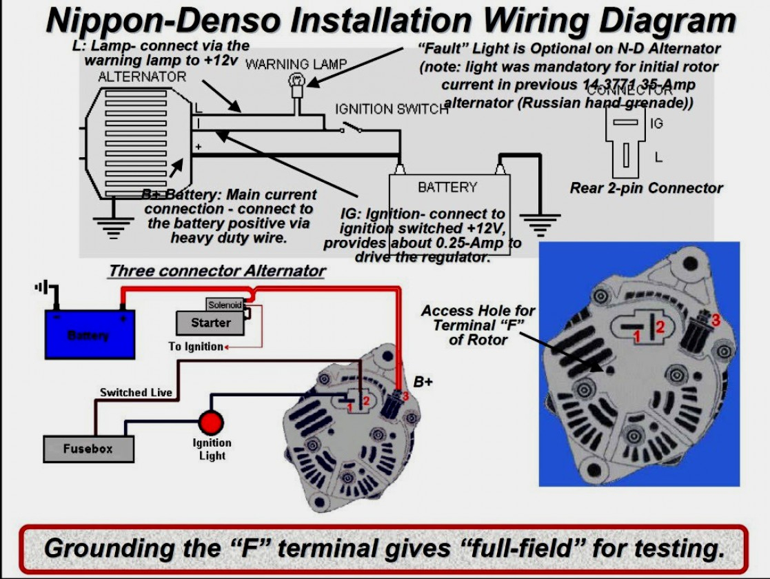
Wiring a 3 wire alternator with an idiot light an idiot light for your alt is a great idea. Behind grating to remove, replace or fix the wiring in an automobile, having an accurate and detailed toyota 3 pin. When you make use of your finger or perhaps the actual circuit with your eyes, it is easy to mistrace the circuit.
A wiring diagram usually gives information not quite the relative slant and accord of devices and. It immediately tells you when your alt stops working and can give you a heads up if you ever kick your serp. The first is the large lug that connects to the battery.
The circuit comprises three main wires: The circuit comprises three main wires: On the clip, you have a #10 wire and a #16 (or so).
This is the main current feed that charges the. The other terminal is the exciter. Connect the opposite end of this wire to the starter solenoid.
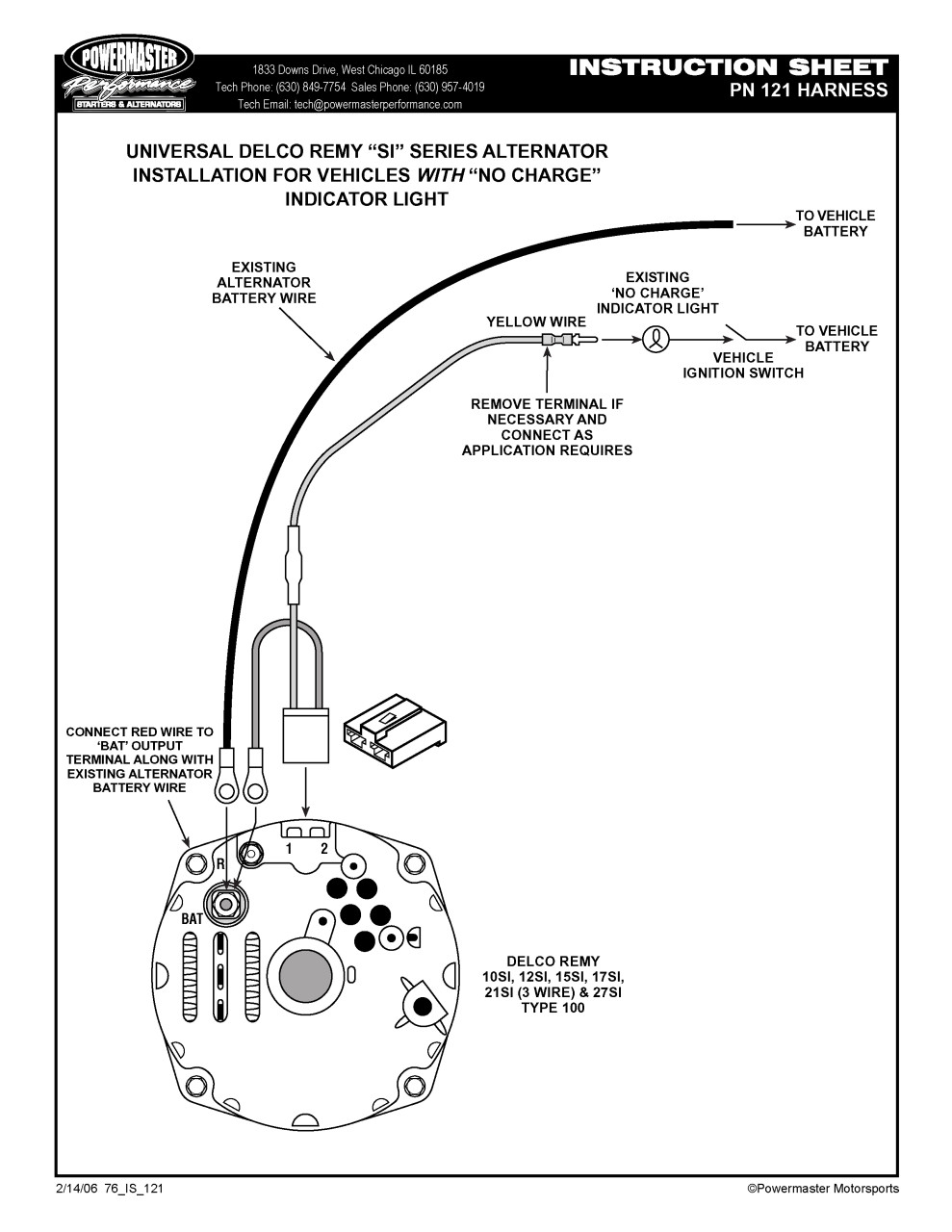
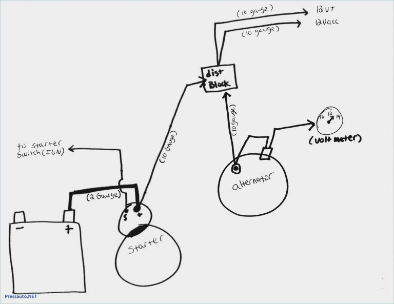
Basic wiring diagram to , replace the alternator and the exciter wire pigtail. Step 2 connect a length of 10 gauge wire to the output stud on the back of the alternator using a solderless ring connector. But, it doesn’t imply link between the wires.
And connect the red wire to the output side of the alternator 10/32 stud, take the long wire and connect to the + side of the coil. There will be main lines that are represented by l1, l2, l3, and so on. Each part ought to be placed and linked to other parts in specific way.
You will be capable to know exactly when the tasks should be completed, that makes it much simpler for you personally to correctly control your time and efforts. Collection of three wire alternator wiring diagram. It shows the components of the circuit as simplified shapes and the facility and signal associates amongst the devices.
A wiring diagram is a simplified traditional pictorial depiction of an electric circuit. Delco 3 wire alternator wiring diagram sample. You simply require to have a great comprehension on.
July 14, 2020·wiring diagramby hadir. When you make use of your finger or perhaps the actual circuit with your eyes, it is easy to mistrace the circuit. Internally regulated alternators have 3 wires the bat terminal which is the output wire terminal 1 which is the excite wire terminal 2 which is the sense wire.
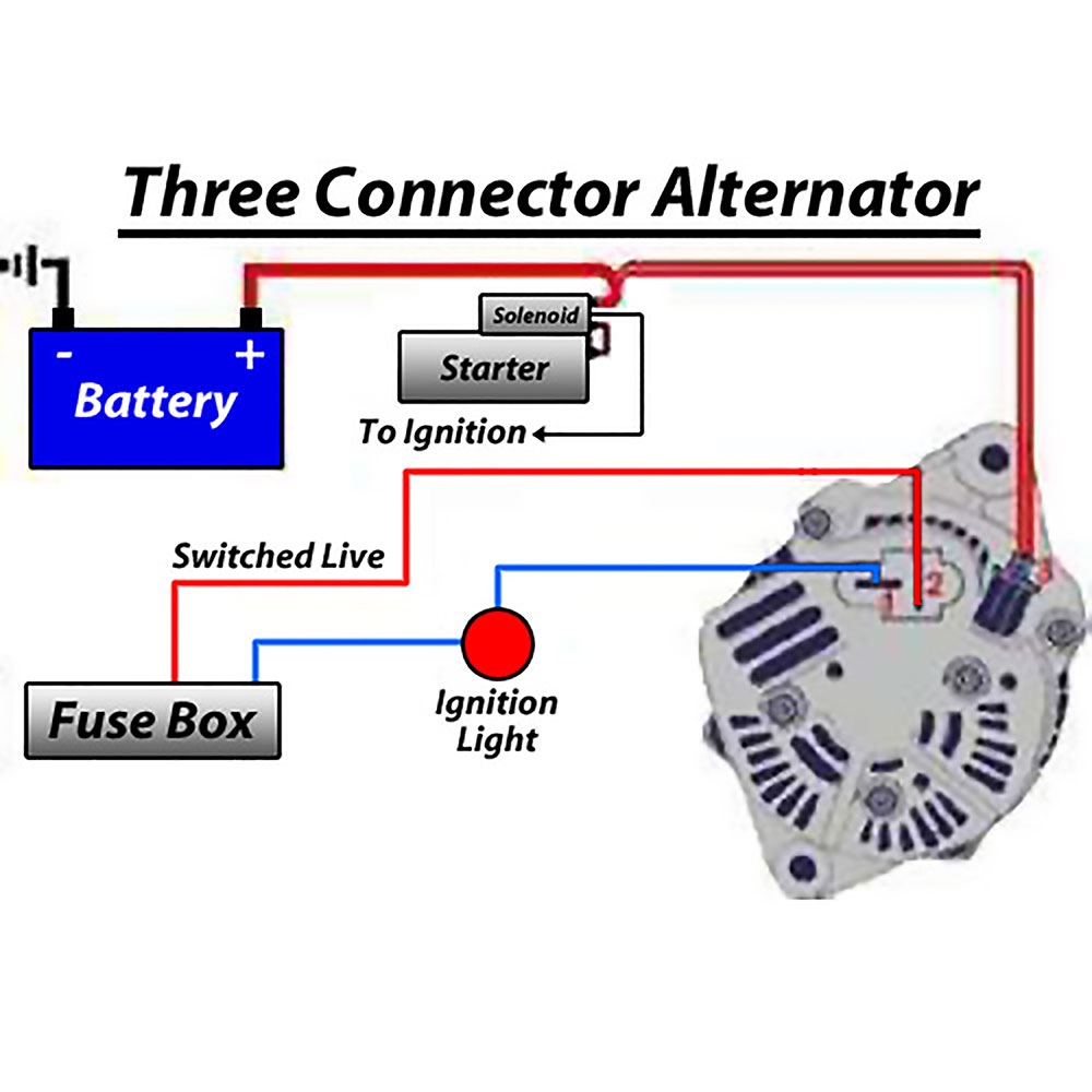
On a three wire you have the #10 output wire. If not, the arrangement will not work as it should be. Simply connect to the same terminal as the positive battery cable.
Print the wiring diagram off plus use highlighters to trace the signal. This is what excites the field of the alternator. Ford 3 wire alternator wiring diagram from fordnews.org.
The battery positive wire connects to the starter. It represents the physical parts of the electrical circuit as geometric forms, with the real power and connection connections in between them as thin sides. The ignition input wire is attached to the engine.
Fold the #10 wire over and put a lug on it to connect to the same point as the output wire on the alternator. The voltage sensing wire connects to the battery, and the. It is really simple to draw a wiring diagram;
On the smaller wire, you run this to the ignition switch and 12 volts. The purpose is the very same: Most modules use an internal driver to turn the alternator’s field circuit on and off.
Wiring Diagram For A Gm 3 Wire Alternator Database Wiring Diagram Sample

3 Wire Gm Alternator Wiring Wiring Forums

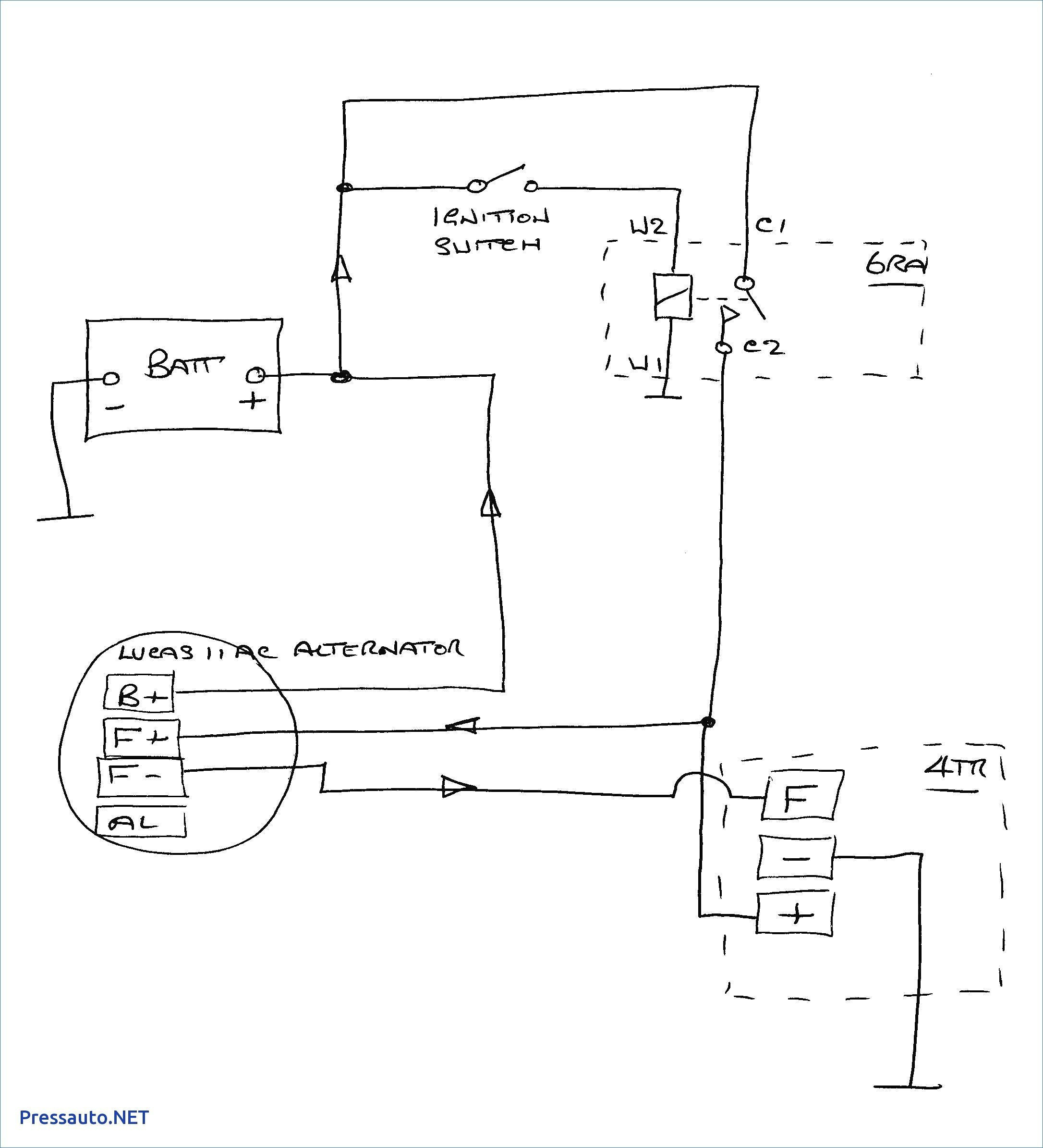
Lucas 3 Wire Alternator Wiring Diagram For Your Needs
3 Wire Alternator Wiring Diagram Diagram Stream
[DIAGRAM] 140 Amp 3 Wire Alternator Diagram FULL Version HD Quality Alternator Diagram
20 New Chevelle Wiring Harness

Delco 3 Wire Alternator Wiring Diagram Free Wiring Diagram

Gm 3 Wire Alternator Wiring Diagram Cadician's Blog
Gm 3 Wire Alternator Wiring Diagram Fuse Box And Wiring Diagram

Delco Remy 3 Wire Alternator Wiring Diagram Wiring Diagram And Schematic Diagram Images

Delco 3 Wire Alternator Wiring Diagram Collection Wiring Diagram Sample

Gm 3 Wire Alternator Wiring Diagram Cadician's Blog
Ford 3 Wire Alternator Wiring Diagram Database Wiring Diagram Sample

Lucas 3 Wire Alternator Wiring Diagram For Your Needs

Delco Alternator Wiring Diagram Collection

Delco Remy Alternator Wiring Diagram 3 Wire WIRGREM
Amp Meter With Alternator Wiring Chevy 3 Wire Wiring Diagram Detailed 3 Wire Alternator
Acdelco 3 Wire Gm Alternator Wiring Wiring Diagram Delco Alternator Wiring Diagram Wiring
Ac Delco 3 Wire Alternator Wiring Diagram Wiring Schema